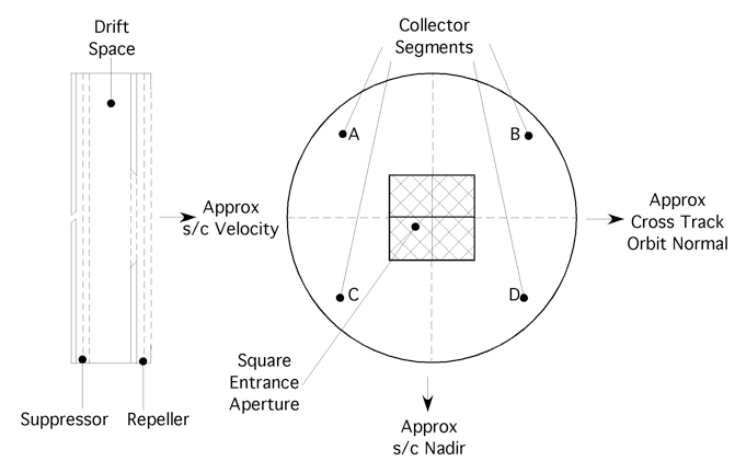
The Ion Drift Meter is a planar sensor that presents a square aperture to the incoming plasma stream that is intersected by a number of planar semi-transparent conducting grids and a solid segmented collector. The collector segments are arranged such that the cuts lie approximately along the satellite nadir and the orbit normal, which define the local vertical and horizontal directions perpendicular to the satellite motion. Two schematic views of the IDM sensor are shown in figure 4.

Figure 4. Schematic cross-section and front view of the ion drift meter.
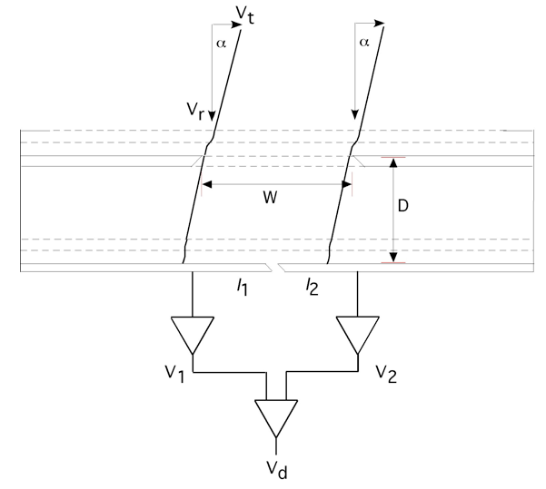
The sensor is mounted to view approximately along the satellite velocity through a larger aperture plane that provides a uniform planar electrical ground reference potential. Two planar grids are placed prior to the entrance aperture to prevent the passage of light ion species. To ensure that no internally applied potentials influence the ambient external plasma the outermost grid, which is coplanar with the aperture plane, is always tied to reference ground, as is the aperture plane. This suppressor grid is biased at -12 volts to prevent access of ambient thermal electrons to the collector and to suppress electrons liberated from the collector by solar euv radiation. Figure 5 shows a schematic cross-section and the O+ beam trajectory, in the plane of the satellite motion and the local vertical. Also shown is the electrical configuration indicating the current measured by logarithmic electrometers that provide the inputs to a linear difference amplifier.

Figure 5. Ion beam trajectories and electronic configuration for the IDM.
It can first be easily seen that a simple trigonometrical relationship exists between the component of the ion velocity normally incident on the sensor aperture and the transverse component of the ion velocity.

The primary task is to determine the arrival angle a, of the plasma from knowledge of the asymmetry in the collector currents and . It can be seen that

Thus from a measurement of the current ratio and knowledge of the sensor dimensions the tangent of the ion beam arrival angle can be determined and thus the transverse component of the ion drift can be derived.
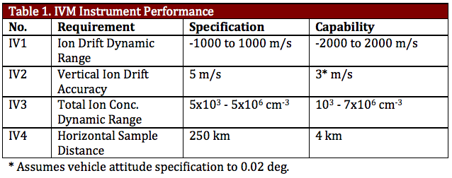
The RPA utilizes an automatic ranging linear electrometer to measure the ion current for discrete values of the retarding potential that may specified by ground command and stepped at a 32 Hz rate. A nominal sweep sequence will comprise 16 points, recorded with 14-bit accuracy and executed in 0.5 seconds. The IDM utilizes two logarithmic electrometers that may be engaged to measure currents from collector segments that are alternately horizontal and vertical in the transverse direction. These signals provide the inputs to a linear difference amplifier that directly provides a signal proportional to the tangent of the ion arrival angle. The difference amplifier is sampled at 32 Hz with 14-bit accuracy, providing alternating horizontal and vertical arrival angles that provide a measure of the dynamic stability of the ionosphere and may be averaged to provide the transverse ion drift components that accompany the ram drift component derived by the RPA. The instrument performance capabilities are shown in Table 1.

IVM – References
Heelis, R.A. and W. B. Hanson (1998), Measurements of Thermal Ion Drift Velocity and Temperature Using Planar Sensors, Measurement Techniques in Space Plasmas: Particles, Geophys. Monogr. Ser., 102, AGU, 61.