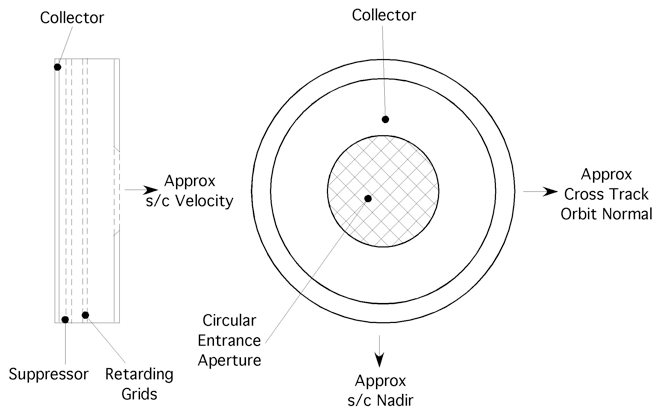
The Retarding Potential Analyzer is a planar sensor that presents a circular aperture to the incoming plasma stream that is intersected by a number of planar semi-transparent conducting grids and a large solid collector. Two schematic views of the RPA sensor are shown in figure 2.

Figure 2. Schematic cross-section and front view of the retarding potential analyzer.
The sensor is mounted to view approximately along the satellite velocity through a large aperture plane that provides a uniform planar electrical ground reference potential. Grounded grids cover the entrance aperture to ensure that no internally applied potentials influence the ion beam trajectories prior to entering the sensor. Inside the sensor the ion beam traverses a series of semi-transparent grids before impacting the collector. The retarding grids are biased at potentials between 0 and 25 volts and thus control the minimum energy that the ions must posses to reach the collector. A suppressor grid prior to the collector is biased at -12 volts to reject ambient electrons and suppress photoelectrons ejected from the collector.
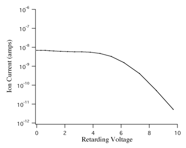
A current-voltage characteristic is obtained by measuring the ion current while the retarding voltage moves over a series of predetermined discrete levels. Retarding voltage sequences are chosen to optimize the sensor performance for the changing conditions expected in the ionosphere over a substantial part of a solar cycle. Figure 3 shows a simulated data curve obtained assuming a total ion concentration or 105 cm-3 with 20% H+ and 80% O+. This current-voltage characteristic has a well-known functional form that can be fitted to retrieve the ion drift component along the sensor look direction, termed , the ion temperature and the major constituent ions. The current at zero retarding voltage is used to derive the total ion number density.

Figure 3. RPA current-voltage characteristic typical of topside ionosphere.